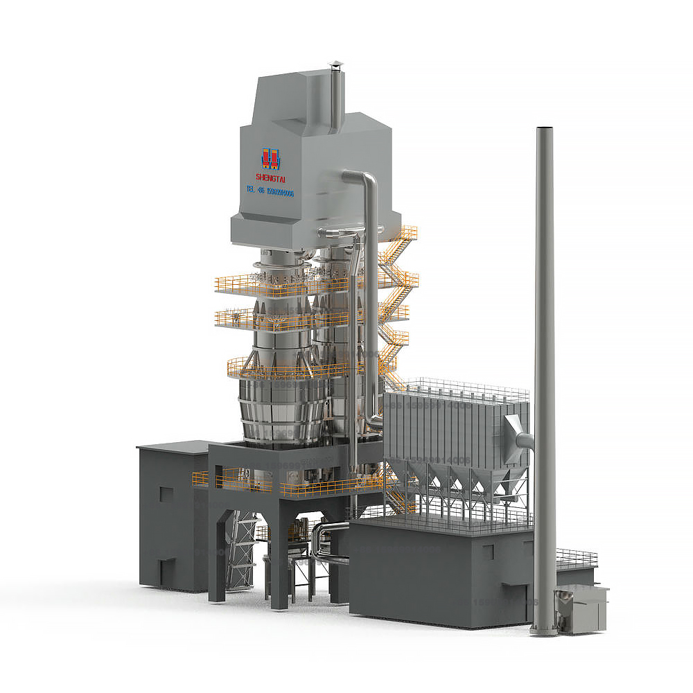
Dual-Chamber Regenerative Shaft Kiln for Lime Calcination-Lime Kiln Manufacturer
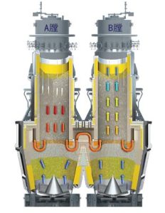
The kiln employs two interconnected chambers (Chamber A and Chamber B) for lime calcination. The calcination zones at the bottom of both chambers are connected, allowing materials to descend through both chambers simultaneously.
Operational Cycle
- Calcination in Chamber A:
- Combustion air and fuel flow co-currently with the material in Chamber A.
- The highest-temperature flames contact cooler, heat-absorbing raw materials, while relatively lower-temperature combustion gases interact with partially calcined materials, ensuring uniform heating and high thermal efficiency.
- Combustion byproducts and CO₂ released from decomposition travel through the connecting channel into Chamber B.
- Regeneration in Chamber B:
- Chamber B acts as the regenerative chamber, where limestone absorbs heat from exhaust gases, cooling the gases to lower temperatures.
- The stored heat in the material is later used to preheat combustion air in the next cycle.
- Cycle Reversal:
- Roles alternate periodically: Chamber A becomes the regenerative chamber, while Chamber B becomes the combustion chamber.
- This cyclic operation enables continuous calcination with minimal heat loss.
Key Features
a. Co-current flow of combustion gases and limestone in the calcination zone.
b. Regenerative heat recovery from all combustion gases during preheating.
Advantages of Dual-Chamber Design
- Ideal for high-activity lime production: Optimized for lightweight calcined lime, high-activity lime, and dolomitic lime.
- Lowest heat loss: Superior to all existing lime kiln types due to regenerative heat exchange.
- Uniform product quality: Eliminates under-burning and over-burning.
Comparative Analysis of Calcination Modes
Refer to Figures 1 & 2 for temperature profiles (Green: Material/Product; Red: Combustion Air & Exhaust; Blue: Cooling Air).
- Counter-current Calcination (Fig. 1):
- Separation of gas and material temperature curves.
- Shortened calcination reaction time, inefficient heat utilization.
- Results in low activity, uneven quality (under/over-burned products).
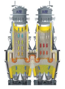
- Co-current Calcination (Fig. 2):
- Gas and material flow in the same direction, ensuring uniform gas distribution.
- Prolonged exposure to high-temperature gases extends the calcination zone.
- Delivers high-activity lime (≥370ml) with consistent quality and no defects.